
Size a generator cable by dividing the load in watts by the voltage to get the design current (Ib), then run three checks before you commit to a conductor: pick a protective device rated In at or above Ib, confirm the derated tabulated rating Iz still exceeds In once you’ve applied ambient, grouping, and insulation factors, and check the voltage drop stays within 3% for lighting or 5% for other circuits. Consult BS 7671 for the correction tables and BS 7909 for event-specific earthing and cable guidance, since generator supplies carry their own RCD and earthing considerations that mains-fed circuits don’t.
TL;DR:
- Protective device ratings should meet or exceed the calculated design current, with a typical safety margin pushing the breaker to 32 A for a 26.1 A load.
- Correction factors for ambient temperature, grouping, and insulation are frequently underestimated, which may reduce the cable’s derated capacity and impact sizing.
- Voltage drop must be carefully checked over the actual run length, especially for long feeders, as it can exceed limits even if thermal ratings are acceptable.
- RCD protection of 30 mA is generally mandatory for temporary generator circuits to ensure safety under lower fault current conditions.
- Use cables suited to the environment and installation method, such as rubber-sheathed flexible cables for temporary setups and armored cables for buried or semi-permanent routes.
Table of Contents
- How do you calculate generator cable sizing step by step?
- What are the mandatory checks for Ib, In and Iz?
- How do you check voltage drop on a generator circuit?
- What RCD and earthing rules apply to generator supplies?
- Which cable types and installation methods suit generator runs?
- Which calculators and site checks confirm the sizing is correct?
- How does ambient temperature change generator cable ratings?
- How does surrounding material affect cable thermal rating?
- Copper or aluminium: which suits generator cable runs?
- What standards beyond BS 7671 and BS 7909 apply here?
- Why compact worked examples beat generic sizing charts
- Sources
- FAQ
How do you calculate generator cable sizing step by step?
Take a 6 kW single-phase load running off a generator at 230 V. Divide watts by volts: 6,000 ÷ 230 gives a design current (Ib) of 26.1 A.
- Select the protective device (In). The nearest standard UK breaker rating above 26.1 A is 32 A, so In = 32 A. That satisfies the first rule: In ≥ Ib.
- Apply correction factors. Say the cable runs clipped direct at a typical ambient temperature alongside other loaded circuits, with no thermal insulation and a standard protective device. Apply corresponding correction factors to find the required tabulated rating.
- Pick the cable. Reading Appendix 4 of BS 7671, a 6 mm² copper twin and earth clipped direct typically offers around 47 A tabulated, comfortably above the 42.6 A requirement.
- Check voltage drop. At roughly 7.3 mV/A/m for 6 mm², over a 25 m run: (7.3 × 26.1 × 25) ÷ 1000 = 4.76 V, which is 2.1% of 230 V, well inside the 5% general limit.
The final choice is 6 mm² copper on a 32 A device, a sizing sequence worth memorising because it’s the exact order every calculator on the market runs through, according to worked examples from NAPIT and Professional Electrician.
What are the mandatory checks for Ib, In and Iz?
Every generator circuit has to satisfy Ib ≤ In ≤ Iz, and separately, the adiabatic check I²t ≤ k²S² for fault protection. Get the terminology straight before touching a table:
- Ib is the design current, the actual load current in amps.
- In is the rated current of the protective device (the fuse or breaker).
- It is the tabulated current-carrying capacity of the cable under standard reference conditions.
- Iz is the derated capacity: It × Ca × Cg × Ci × Cc, and this is the figure that must sit at or above In.
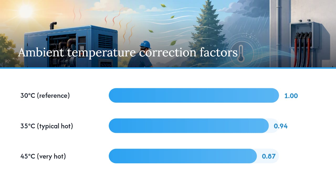
Correction factors are where most sizing errors happen. Ambient temperature (Ca) typically ranges from 1.0 at 30°C down to around 0.87 at 45°C for PVC cable. Grouping (Cg) can drop below 0.7 once four or more circuits share a tray. Thermal insulation (Ci) is brutal: a cable fully surrounded by insulation for more than half a metre can see its rating cut roughly in half, according to derating guidance from Elec-Mate. Device type (Cc) matters too, since some protective devices demand a higher safety margin than others.
The adiabatic equation, k²S² ≥ I²t, confirms the conductor can survive a fault for the time it takes the protective device to clear it. It matters most on longer generator feeders where fault current is lower and clearance times run longer than on a mains-fed circuit. Practical derating guidance points out that cumulative correction factors are consistently the most under-applied part of the calculation, not the initial current lookup.
How do you check voltage drop on a generator circuit?
Voltage drop is calculated as (mV/A/m × I × L) ÷ 1,000, where mV/A/m is read straight from the BS 7671 tables for your chosen conductor, I is the design current, and L is the route length in metres. Get this wrong on a long generator feeder and the far end of the run under-performs even though the cable is technically rated for the current.
BS 7671 sets the ceiling at 3% for lighting circuits and 5% for everything else, which at a 230 V supply works out as follows:
| Circuit type | Percentage limit | Volts at 230 V |
|---|---|---|
| Lighting | 3% | 6.9 V |
| Other circuits (sockets, motors, distribution) | 5% | 11.5 V |
Motor loads complicate the picture because starting current can run five to six times the running current for a second or two. That transient doesn’t usually force a bigger cable on its own, but it does mean the protective device has to tolerate the inrush without nuisance-tripping while the cable’s steady-state Iz still governs the conductor size. On long generator runs across a site, a common mistake is sizing purely on current-carrying capacity and only checking volt drop as an afterthought. Do it the other way round on anything over 30 to 40 metres. If the drop calculation forces a bigger conductor than the thermal check does, the volt drop figure wins and you upsize.
What RCD and earthing rules apply to generator supplies?
Temporary generator-fed final circuits almost always need 30 mA RCD protection under BS 7671 Regulation 551.4.4.2, because generators typically deliver lower fault current than a mains supply and can’t always guarantee disconnection times through overcurrent devices alone.
Earthing needs a deliberate decision, not a default. Options include:
- A TN-S arrangement with a neutral-earth link at the generator and bonding carried through, common for smaller standalone sets.
- A separate earth electrode, sized against target resistance, used where the generator forms an islanded system with no upstream earth reference.
- Selective protection using nested RCDs, where a 100 mA or 300 mA device sits upstream of individual 30 mA final-circuit RCDs to prevent one faulty appliance from dropping the whole supply.
Electrode resistance targets vary by scenario. BS 7430 references 20 Ω as a common benchmark, though some islanded TN-S generator setups with RCD backup are accepted at higher resistances when the rationale and test results are documented properly.
Pro Tip: Test earth electrode resistance before the event starts, not during setup under time pressure. A reading that looked fine on last month’s job can drift after a wet week or a change of ground conditions.
Which cable types and installation methods suit generator runs?
Cable choice depends on whether the run is temporary or semi-permanent, and on how it’s routed.
- H07RN-F rubber-sheathed flexible cable is the standard choice for temporary event runs, since it tolerates repeated flexing, crowd traffic, and outdoor exposure far better than standard PVC flex.
- SWA (steel wire armoured) cable suits buried or semi-permanent feeders where mechanical protection against impact or rodent damage matters.
- Multicore cable is common for lower-current distribution runs; single-core conductors, often run in parallel, become necessary once current climbs high enough that a single multicore gland or termination can’t cope.
Installation method changes the tabulated rating (It) significantly. Clipped direct, conduit, and tray-mounted methods each carry different reference method codes in BS 7671 Appendix 4, and grouping several cables on one tray drops the usable rating fast. For buried SWA, BS 7909 guidance recommends adequate burial depth and marker tape, plus ramping or matting anywhere a temporary cable crosses a walkway. More detail on these constructions is covered in Jakspartypower’s guide to temporary power cabling types.
Which calculators and site checks confirm the sizing is correct?
Manual calculation is the right way to learn the method, but cross-checking with a calculator catches arithmetic slips before they reach site. Reputable tools worth using:
- The Atlas Copco electric cable sizing calculator runs current-carrying and volt-drop checks against generator-specific inputs.
- The WireWrite UK cable sizer applies BS 7671 correction factors automatically and returns the smallest legal conductor, rounding up when a result sits on the borderline.
On site, verification follows a fixed sequence: draw or check the single-line diagram, verify continuity of the circuit protective conductor, carry out the RCD trip test, take an earth electrode resistance reading, confirm phase rotation on three-phase supplies, then run a functional load test before handover. Jakspartypower’s electricians apply this sequence on every event fit-out across decades of contracting work, and a walk-through of the process sits in Jakspartypower’s event electrical equipment inspection guide.
Pro Tip: Keep a laminated single-line diagram in the generator cabinet itself. It’s the fastest way for a second engineer to verify your work without you standing there explaining it.
How does ambient temperature change generator cable ratings?
Tabulated ratings in BS 7671 assume a 30°C reference ambient for most general cable installations. Generators, and the cables feeding them, rarely sit in that comfortable middle ground.
A generator running inside a plant enclosure, under canvas at a summer festival, or tucked into a marquee corner easily hits 35°C to 40°C ambient, sometimes higher next to the engine casing itself. Every degree above the 30°C reference drags the correction factor (Ca) down: a typical PVC cable factor falls from 1.0 at 30°C to around 0.94 at 35°C and closer to 0.87 at 45°C. Copper’s resistance rises with temperature too, so a hot cable run doesn’t just carry less current safely, it also drops slightly more voltage for the same load.
Winter outdoor events swing the other way. Ambient correction factors above 1.0 exist for low temperatures, but most designers ignore the uplift and size for the worst case anyway, since a generator’s own exhaust heat can push local air temperature up regardless of the weather outside. The practical habit worth adopting: measure or estimate the actual temperature at the cable’s location, not the temperature at the generator control panel three metres away. A cable coiled near a canopy roof in direct sun reads hotter than one shaded underneath a stage riser, and that difference is enough to shift a borderline sizing decision from “fine” to “undersized.”
How does surrounding material affect cable thermal rating?
Thermal resistivity of whatever surrounds a cable governs how efficiently it sheds heat, and it’s a factor installers underestimate constantly on generator jobs.
A cable clipped to open air dissipates heat freely, which is why clipped-direct reference methods carry the highest tabulated ratings for a given size. Bury that same cable in ordinary soil and its effective rating drops, because soil traps heat far less efficiently than air, and dry sandy soil traps it worse still than damp clay. Push the cable into a bundle on a tray with several others, wrap it in thermal insulation inside a temporary structure, or run it through ducting with poor airflow, and the surrounding thermal resistivity climbs further, forcing the tabulated rating down again, a concern covered in the event textile solutions checklist: A hotel & restaurant guide.
The insulation case deserves particular attention on event work. A cable fully surrounded by insulating material for a run of more than roughly half a metre can see its effective rating cut by around half, according to Elec-Mate’s derating guidance. That scenario shows up more often than installers expect: a cable pushed through foam-lined stage decking, packed against acoustic panelling in a temporary structure, or buried beneath insulating floor matting at an indoor arena event. Cable trays present a gentler version of the same problem, where multiple cables stacked close together trap heat between them even without solid insulation in contact.
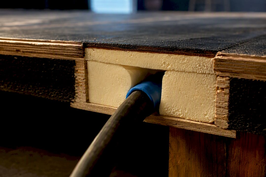
The fix is straightforward once you spot the risk: route around insulated sections where possible, or apply the correction factor and upsize the conductor rather than assume open-air ratings apply everywhere along the run.
Copper or aluminium: which suits generator cable runs?
Copper remains the default choice for generator feeders, and for good reason: it carries more current for a given cross-sectional area, terminates reliably in standard glands and lugs, and tolerates the repeated connect-disconnect cycle typical of temporary event work without the connection degrading.
Aluminium conductors turn up on larger permanent installations, particularly high-current feeders and busbar runs, where the cost saving over copper at scale becomes significant and the cable stays put for years rather than being coiled and re-laid every weekend. Aluminium needs a larger cross-sectional area than copper for the same current, roughly one and a half times the size for an equivalent rating, and it demands specific bimetallic or anti-oxidant terminations to prevent galvanic corrosion at the joint. That corrosion risk is exactly why aluminium suits fixed installations better than portable ones: a termination tightened once and left alone behaves very differently to one that gets unplugged, coiled, and reconnected at every event.
For temporary generator supplies, where cables get flexed, coiled, and re-terminated repeatedly, copper’s mechanical reliability outweighs any weight or cost advantage aluminium offers. Where a permanent power installation at a venue justifies the larger aluminium feeders, that’s a design decision worth making with a qualified engineer rather than defaulting to whatever was used last time.
What standards beyond BS 7671 and BS 7909 apply here?
BS 7671 and BS 7909 cover UK installation practice, but generator cable sizing sits inside a wider standards landscape worth knowing, particularly on projects with international equipment or specifications.
The IEC 60364 series forms the international basis that BS 7671 itself draws heavily from, and it’s the reference point most European and Commonwealth wiring regulations align to in some form. For generator sets specifically, BS 7698 and its IEC equivalent cover the machines themselves, their protection systems, and their interaction with connected loads. In the US, the National Electrical Code (NEC) governs generator and cable sizing under a different tabulated-rating structure with its own ampacity tables, which means a cable sized correctly to NEC figures cannot be assumed compliant against BS 7671 tables, and vice versa. The two systems use different reference conditions and different derating philosophies.
For anyone working across jurisdictions, or specifying equipment manufactured to a different standard than the installation it’s feeding, the practical rule is simple: identify which standard governs the actual site, and size against that standard’s own tables rather than translating figures from one system into another. Cross-standard conversions of current ratings are a common source of subtle undersizing, since the reference conditions rarely match exactly.
Why compact worked examples beat generic sizing charts
The industry has no shortage of generic sizing charts pinned to site cabin walls, and most of them are wrong for the specific job in front of you. A chart built on standard 30°C ambient, no grouping, and open-air installation tells you almost nothing useful about a cable running through a marquee in July, bundled with three other feeders on a tray. That’s the gap a compact worked example closes: it forces you to plug in your actual ambient, your actual grouping, your actual route length, rather than borrowing someone else’s assumptions.
The most overlooked step, based on where errors actually cluster, isn’t the initial Ib calculation. It’s the cumulative correction factor. Engineers get the watts-to-amps sum right nearly every time, then apply one derating factor and stop, forgetting that ambient, grouping, and insulation all stack multiplicatively. Run the full Iz = It × Ca × Cg × Ci × Cc chain every time, even when a single factor looks negligible on its own.
If there’s one habit worth prioritising above all else, it’s this: check voltage drop independently of thermal rating, every single time, rather than assuming a cable that passes the current check automatically passes the drop check. On long generator runs they diverge more often than most designers expect, and the drop calculation is the one that tends to get skipped under time pressure.
— Rob
Sources
FAQ
How do I calculate the cable sizing for a generator?
Divide the load in watts by the supply voltage to get the design current (Ib), select a protective device rated In at or above that figure, then apply BS 7671 correction factors to confirm the derated Iz still exceeds In before checking voltage drop.
What size wire should I use for a generator?
There’s no single fixed size. It depends on load current, run length, ambient temperature, and grouping, which is exactly why the BS 7671 Appendix 4 tables and a proper worked calculation matter more than a rule-of-thumb chart.
What size wire should I use for a 20 kW generator?
A 20 kW single-phase load at 230 V gives a design current of roughly 87 A (20,000 ÷ 230), which typically needs a 100 A protective device and a conductor sized against that In after applying ambient and grouping correction factors, then checked for voltage drop over the actual run length.
What size wire should I use for a 10 kW generator?
A 10 kW single-phase load at 230 V gives a design current of around 43.5 A, usually paired with a 50 A protective device, with the final cable size confirmed only after running the correction factors and voltage drop check specific to the installation.
Do generator circuits always need RCD protection?
Temporary generator-fed final circuits generally need 30 mA RCD protection under BS 7671 Regulation 551.4.4.2, because generator fault current and disconnection characteristics differ from a mains supply.
Getting a generator cable calculation right on paper is only half the job. Hiring pre-tested, correctly rated cable and distribution equipment from a specialist removes the guesswork on site entirely, and Jakspartypower’s generator hire service pairs the right kit with the standby engineering support to back it up throughout the event.