
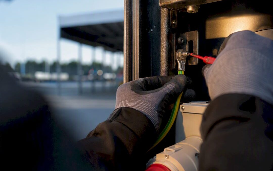
Earthing gives fault current a route back to the source so a protective device can trip and cut the supply. Bonding equalises the potential between metal parts so touching two of them at once cannot deliver a shock. Both are required by BS 7671 in almost every UK installation, and neither one can substitute for the other. Get either wrong and the protective system as a whole stops doing its job.
TL;DR:
- Proper sizing of bonding conductors on PME systems typically requires 10 mm² copper to handle potential fault conditions safely.
- Bonding is continuous and instant, preventing voltage differences, while earthing responds to actual faults by discharging fault current within regulatory disconnection times.
- Failures often occur when clamps sit on painted or corroded pipes, or when bonding is downstream of valves, both of which compromise low resistance paths.
- Temporary power setups demand careful verification of generator earthing and bonded metalwork, especially with different earthing types and pipe materials.
- Accurate testing and documentation of bonding continuity and earth loop impedance are crucial for compliance and preventing dangerous voltage differences.
Table of Contents
- Bonding vs earthing: the core difference explained
- Protective bonding: main, supplementary, and how it’s labelled
- Earthing vs bonding: function, timing and outcome side by side
- BS 7671 rules and conductor sizing you need to get right
- Applying the rules on site and at temporary power events
- How bonding and earthing failures show up on testing
- Common mistakes and a quick on-site checklist
- Practitioner view: earthing and bonding on event power sites
- Minimum compliance isn’t the same as good practice
- Where to check the detail yourself
- Sources
- FAQ
Bonding vs earthing: the core difference explained
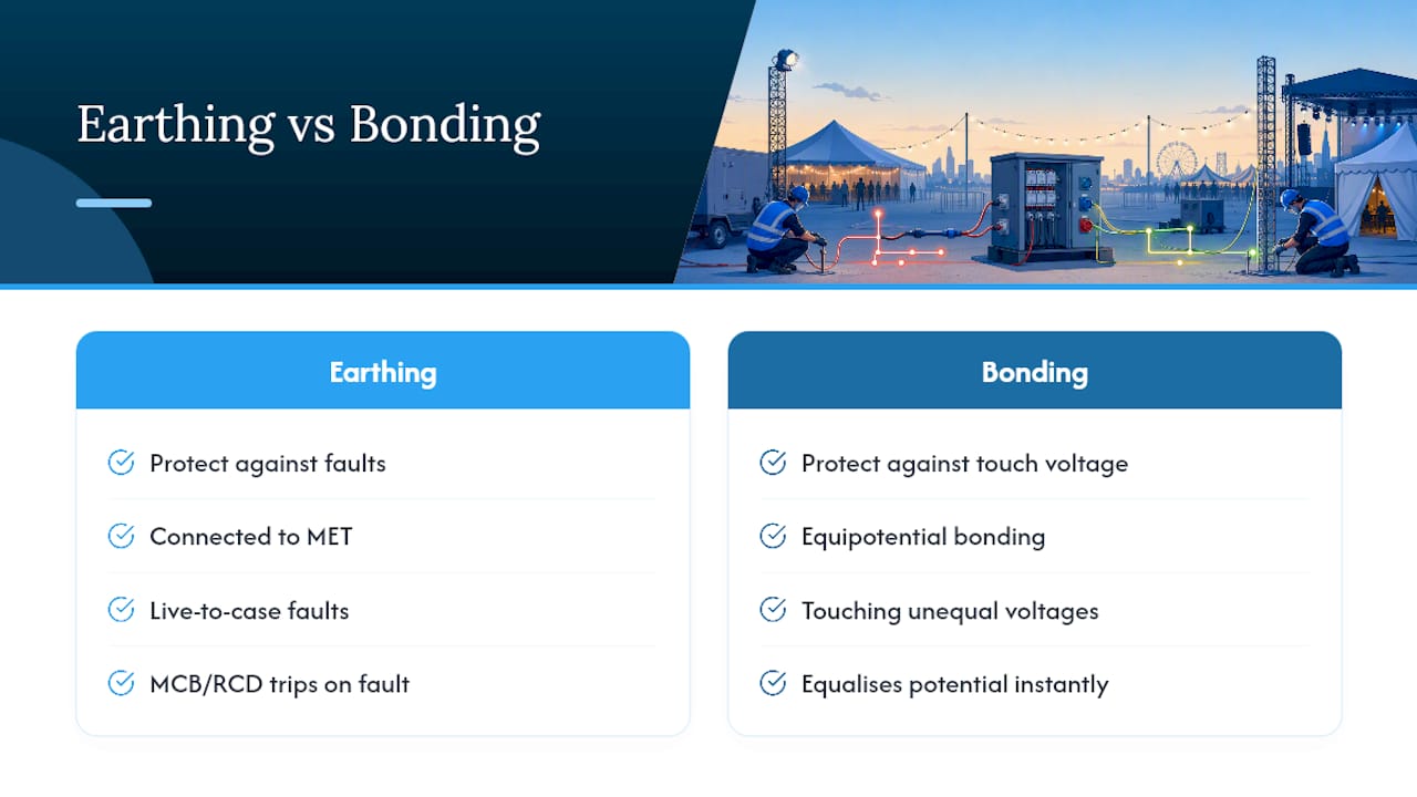
Earthing and bonding solve two different problems, even though they end up connected to the same terminal in most installations. Earthing exists to protect against a fault. Bonding exists to protect against the split second when someone touches two things that should be at the same voltage but are not.
Every exposed-conductive-part, the metal casing of a washing machine, a light fitting, a consumer unit, gets connected to the main earthing terminal (MET) so that if a live conductor faults to that metalwork, current has somewhere low-resistance to go. That current flow is what makes an MCB or RCD trip: no return path, no fault current, no disconnection, and a live case stays live indefinitely. BS 7671’s Table 41.1 sets maximum disconnection times for this, typically 0.4 seconds for a 230V TN system and 0.2 seconds for TT, because the longer a fault persists, the higher the risk of a lethal shock or fire.
How that return path behaves depends heavily on which earthing system feeds the property. Most UK homes on newer estates run on PME (Protective Multiple Earthing, technically TN-C-S), where the supplier combines neutral and earth conductors somewhere upstream and gives you a solid, low-impedance earth reference. Rural properties and some older or off-grid sites run TT, where the installation earths through a local rod rather than the supplier’s network. TT systems rely far more heavily on RCD protection because the earth loop impedance through a rod is usually too high to guarantee fast disconnection using overcurrent devices alone. Get the earthing type wrong when specifying protection and you can end up with a system that technically has an earth but never trips fast enough to matter.
Protective bonding: main, supplementary, and how it’s labelled
Bonding is not about clearing a fault. It is about preventing a dangerous voltage difference from ever existing between two touchable metal parts in the first place, whether or not anything has failed. This matters because some metalwork in a building, water pipes, gas pipes, structural steel, has no electrical connection to the installation at all but can still become “live” relative to earth if a fault occurs elsewhere on the network. BS 7671 calls this class of metalwork extraneous-conductive-parts, distinct from the exposed-conductive-parts that earthing deals with.
Main protective bonding connects those extraneous parts, incoming water, gas, and sometimes oil pipework, to the MET. IET guidance confirms this is a near-universal requirement, with one notable exception covered later. Supplementary bonding is a more localised measure, applied in specific zones such as bathrooms where the combination of water and skin contact raises the stakes if automatic disconnection can’t guarantee a safe touch voltage. Modern RCD protection often removes the need for it, but that’s a judgement call an electrician has to verify on-site rather than assume, according to practitioner guidance on supplementary bonding.
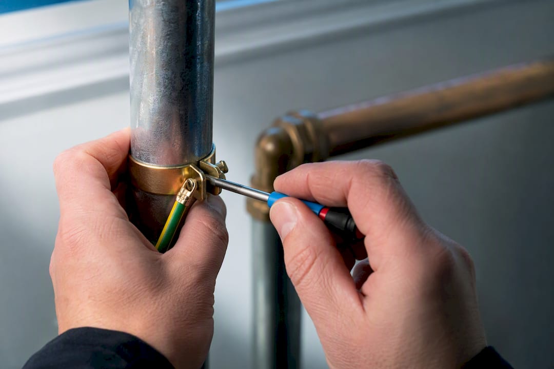
On installation, bonding clamps must sit on a clean, non-corroded section of pipe to form a proper gas-tight connection. Paint or scale under the clamp creates a high-resistance joint that quietly defeats the whole point of bonding while looking fine on a visual inspection. Every bonding clamp and the MET itself should carry the label “Safety Electrical Connection — Do Not Remove” referencing BS 951, precisely so a plumber or builder doesn’t strip it out during unrelated work years later.
Earthing vs bonding: function, timing and outcome side by side
Laid outside by side, the two measures act at different moments and against different risks:
- Trigger: earthing responds to an actual fault current; bonding is passive and works continuously, whether or not a fault exists.
- Purpose: earthing gives protective devices something to disconnect against; bonding stops a dangerous potential difference from forming between accessible parts.
- Typical current involved: earthing deals with fault currents large enough to trip an MCB or RCD; bonding is designed to carry that same fault current briefly without the conductor overheating, but its job is voltage equalisation, not disconnection.
- Timescale: earthing enables disconnection within the limits set by Table 41.1 (commonly 0.4s TN, 0.2s TT); bonding’s protection is instantaneous by design, since the metalwork is already at equal potential before any fault occurs.
- What happens if it’s missing: no earthing means a fault may never clear, leaving live metalwork indefinitely; no bonding means a fault elsewhere can leave two touchable surfaces at different voltages even while the earthing system works exactly as intended.
Picture someone standing in a kitchen touching a metal sink tap with one hand and a faulty appliance casing with the other. Earthing is what eventually clears that fault and trips the circuit. Bonding is what stops the tap and the appliance sitting at meaningfully different voltages in the seconds before that happens. Rely on earthing alone and you’re betting entirely on disconnection speed. Rely on bonding alone and you’ve removed the touch-voltage risk but done nothing to clear the actual fault. UK installations need both operating together.
BS 7671 rules and conductor sizing you need to get right
BS 7671 (18th Edition) sets out the framework installers work to, and a handful of regulations do the heavy lifting. Regulation 411 covers the requirements for automatic disconnection of supply, tying earthing directly to the disconnection times in Table 41.1. Regulation 543 governs the sizing and installation of protective conductors, including bonding conductors, and Table 54.8 gives the specific sizing rule for main protective bonding conductors based on the cross-sectional area of the supply’s neutral conductor.
In practice, most electricians default to a conductor size rather than recalculating from first principles on every job, and there’s good reason for that.
| Scenario | Typical bonding conductor size | Notes |
|---|---|---|
| Domestic PME supply (TN-C-S) | 10 mm² copper | Common default per Table 54.8 guidance to remove sizing ambiguity on PME systems |
| Some non-PME (TT/TN-S) installations | 10 mm² copper minimum | Lower minimum permitted, but must still be checked against the actual supply conductor size |
| Supplementary bonding conductors | Sized per specific circuit and zone requirements | Verified locally; not a fixed default |
PME supplies carry a slightly elevated risk from PEN conductor faults upstream, where a broken combined neutral/earth can push the earthing conductor to a dangerous voltage. That’s precisely why 10mm² has become the practical standard on PME domestic bonding: it comfortably covers the required cross-section and removes any doubt during inspection.
Location matters as much as size. Main bonding connections to incoming water and gas services must be made close to the point of entry to the building, on the consumer’s side of the meter, typically within a short distance recommended by guidance, and onto a clean section of pipe rather than through paint or fitting compound, as confirmed by guidance on the 18th Edition. Every clamp then needs the “Safety Electrical Connection — Do Not Remove” label fitted permanently, not taped on as an afterthought.
Applying the rules on site and at temporary power events
Getting bonding right on a working site is less about the regulation text and more about routing it sensibly and documenting it properly. Bonding conductors should run as directly as possible from the extraneous part to the MET, avoiding unnecessary joints along the way, since every joint is a potential point of increased resistance.
Temporary and event power introduces a wrinkle that domestic wiring rarely deals with: generator earthing. A generator supplying a marquee or outdoor event isn’t automatically tied into the site’s PME earth, and treating it as if it were can create a genuinely dangerous situation if the generator’s neutral and the site’s earth aren’t correctly referenced together. BS 7909 covers temporary electrical systems for events specifically, and it’s worth following rather than adapting domestic practice on the fly.
Practical points that come up repeatedly on event and temporary sites:
- Confirm whether the generator is TN-S (earth via its own frame/electrode) or being run in parallel with a PME supply, since the two need different earthing treatment.
- Check whether a local earth electrode is needed for a standalone generator rather than assuming the supply network provides one.
- Never assume a plastic incoming water or gas service pipe removes the need to bond elsewhere in the system; verify the entire run on-site, check the whole run.
Pro Tip: If a service pipe changes from plastic to metal anywhere between the street and the building, or if you can’t verify the material for certain, bond it anyway and document why. A missed metal section beats an assumption every time an inspector asks about it later.
Where a plastic incoming pipe genuinely runs the entire distance with no metal section, IET guidance confirms bonding that particular service may not be required, but this needs verifying on-site, not assumed from the property’s age or postcode. Anyone routing temporary power cabling across a site should treat that verification as part of the setup, not an afterthought once cables are already run.
How bonding and earthing failures show up on testing
Continuity testing on bonding conductors should return a very low resistance, typically well under 1 ohm on a short domestic run, confirming the conductor and its clamp connections form a genuine low-impedance path rather than a loose or corroded joint. A high or unstable reading almost always traces back to a clamp sitting on paint, corrosion, or a compression fitting rather than clean pipe.
Earth fault loop impedance (Ze and Zs) testing checks the whole path a fault current would actually take, from the point of the fault back through earthing to the source. That figure has to be low enough to guarantee disconnection within the times set by Table 41.1, and a Zs reading that’s borderline high is often the first sign of a poor earthing connection rather than a wiring fault elsewhere.
On an EICR, bonding and earthing problems generate some of the most common observation codes:
- Missing main bonding to water or gas: typically coded C2 (potentially dangerous), requiring remedial action before the report can be marked satisfactory.
- Bonding conductor undersized for the supply: often C3, though context and the specific installation can push it higher.
- Bond connected after an isolating valve or union, rather than on the fixed pipework: a common practical failing flagged in practitioner EICR guidance.
- Missing or illegible safety labels: usually a lower-priority observation, but still noted and correctable cheaply.
Common mistakes and a quick on-site checklist
Most bonding failures trace back to a handful of repeat offenders: clamps fitted over paint or corrosion, bonds connected downstream of an isolating valve instead of the fixed pipe, missing safety labels, and conductors undersized for the supply they’re protecting. None of these are exotic problems, they’re just easy to miss on a walk-through.
- Check presence: is every extraneous-conductive-part actually bonded, water, gas, and any structural metalwork in scope?
- Check size: does the conductor match Table 54.8 for the supply type, PME or otherwise?
- Check continuity: does a test confirm a genuinely low-resistance path, not just a visually connected clamp?
- Check the label: is “Safety Electrical Connection — Do Not Remove” fitted and legible?
- Check RCD protection: where supplementary bonding might be omitted, has that decision actually been verified rather than assumed?
If any of these come back uncertain, that’s the point to bring in a competent electrician rather than guess. Hand them the test readings you do have, continuity figures, Zs results, photos of clamp condition, since that evidence saves a second visit and speeds up any remedial work.
Practitioner view: earthing and bonding on event power sites
Event power throws up bonding and earthing questions that a domestic install never has to answer twice in one week: different generators, different sites, different pipework every job. Field practice on event sites leans on clear labelling and documented checks precisely because temporary setups get handled by multiple crews across a single event, and a bonding clamp that looks fine on Friday needs to still be verified on Saturday morning.
Standby cover during live events means someone is watching earthing and bonding continuity for the whole duration, not just at initial setup. On generator-fed sites, deciding between relying on a supply’s PME reference and fitting a local earth electrode is a judgement made on-site against the specifics of that generator and structure, not a fixed rule applied blind. Anyone inspecting event electrical equipment before doors open should treat bonding continuity as a checklist item, not an assumption.
— Rob
Minimum compliance isn’t the same as good practice
BS 7671 sets a floor, not a target. Defaulting to 10mm² bonding conductors and fitting proper labels costs very little extra and removes doubt at the next inspection, long after anyone remembers which fitting was borderline.
For temporary event power specifically, extra verification and paper records aren’t box-ticking. They’re what protects an organiser when something goes wrong on a site nobody will see again after Sunday.
Where to check the detail yourself
The IET’s BS 7671 FAQ page is the most reliable starting point for definitions and exceptions straight from the standard’s own custodians. For sizing tables and clamp installation detail, the Elec-Mate protective earthing and bonding guide covers Table 54.8 in practical terms. Anyone weighing up supplementary bonding decisions in bathrooms or similar zones should read the APMI guide to main and supplementary bonding. None of these replace a site-specific decision from a competent electrician, but they’re where that electrician’s own reasoning usually starts.
Need power, distribution, or standby cover sorted for an event or temporary installation, with bonding and earthing already handled correctly? Jakspartypower’s event equipment and setup services cover generators, distribution boards, cabling, and on-site standby support across a job, backed by over 40 years of electrical contracting experience behind the equipment.
Sources
- BS 7671 FAQs – Earthing and Bonding — IET
- Earthing and bonding explained — 18th edition prep
- Earth bonding and supplementary bonding — APMI / practitioner guide
FAQ
What are the regulations for earthing and bonding in the UK?
BS 7671 (18th Edition) governs both, with Regulation 411 covering automatic disconnection via earthing and Regulation 543, alongside Table 54.8, setting sizing rules for bonding conductors.
Are bonding and earthing the same thing?
No. Earthing gives fault current a path so protective devices can disconnect the supply; bonding equalises potential between metal parts so a dangerous voltage difference never forms between them.
What is the British standard for earthing?
BS 7671 covers earthing requirements for fixed installations, while BS 7909 specifically addresses temporary electrical systems used for events and similar structures.
Is there a difference between grounding and bonding?
“Grounding” is the American term for what UK regulations call earthing, so the distinction is the same: grounding/earthing clears faults, bonding prevents dangerous touch voltages between accessible parts.
Do plastic water or gas pipes still need bonding?
Where the incoming service pipe is plastic for its entire run with no metal section, bonding that service typically isn’t required, but this must be verified on-site rather than assumed from the pipe material alone.