
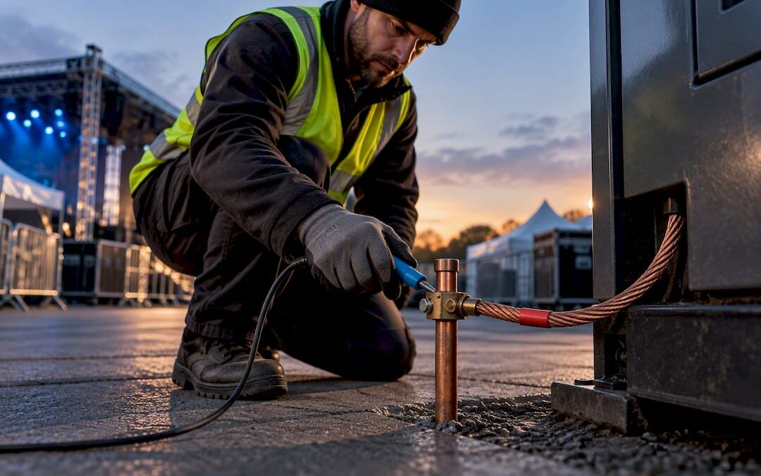
If a generator runs as a switched alternative to the mains, it cannot rely on the distributor’s earth. BS 7671 Regulation 551.4.3.2.1 requires a dedicated means of earthing for the set itself. Where an electrode genuinely cannot be driven, a time-delayed RCD rated at 100 mA or less at the generator output is an accepted short-term control, provided every test result is recorded with a proper earth electrode resistance tester rather than an EFLI instrument.
TL;DR:
- A generator’s earthing method must be deliberately selected based on site conditions, with a proper electrode installed when feasible or a time-delayed RCD as a short-term fallback.
- Testing requires specific equipment: a proper earth electrode resistance tester and a sequence including continuity, polarity, earth resistance, and RCD trip tests, all recorded accurately.
- Common mistakes involve bonding a generator neutral to PME systems while islanded, relying on poor electrode readings, and ignoring circulating currents in parallel or hybrid setups.
- Large events should use site-proven earthing checklists, photograph electrode connections and RCD results, and confirm the generator’s topology before energizing.
- Floating arrangements with RCD protection are only suitable temporarily; permanent setups at venues need engineered electrode systems and regular retesting to ensure safety and compliance.
Table of Contents
- What are the different generator earthing topologies?
- What do BS 7671, BS 7430 and BS 7909 actually require?
- How do you check and design generator earthing on site?
- How do you test and record a generator earthing arrangement?
- What are the common mistakes with generator earthing?
- What does a site-proven earthing checklist look like?
- How deep should a generator earth electrode be driven?
- Do portable and fixed generators need different earthing methods?
- How does generator earthing interact with the building’s own earthing?
- What tests confirm compliance beyond earth resistance?
- What health and safety risks apply to generator earthing work?
- Does generator earthing affect EMI and EMC performance?
- Practical perspective: balancing ideal earthing with event constraints
- How Jaks Party Power supports compliant generator earthing
- Sources
- FAQ
What are the different generator earthing topologies?
Every generator on site falls into one of three broad arrangements, and identifying which one you are looking at is the first job before you touch a test lead. Get this wrong and you either miss a fault path that will not clear, or you spend an afternoon chasing an earth reading that was never meant to protect anyone.
- Floating (IN-S): the generator neutral has no intentional connection to earth or to any electrode. Nothing trips on a single earth fault because there is no return path, which sounds safer than it is.
- Referenced-to-earth (generator electrode / TN-S style): the neutral is bonded to a local electrode, giving protective devices a defined fault path back to the source, much like a conventional TN-S supply.
- TT-like arrangements: the generator neutral is earthed via its own electrode and the installation’s exposed metalwork is also earthed, relying on RCDs rather than high-magnitude fault currents to disconnect.
The trouble with the word “floating” is that installers use it loosely. The IET’s Wiring Matters points out that a neutral-to-earth continuity reading below roughly 0.1 Ω tells you the set is actually referenced, whatever the label on the control panel says. Don’t trust the terminology; measure it.
A genuinely floating alternator can power a job all day without a single trip, which convinces some crews it doesn’t need protecting. It does. Connected equipment still needs a fault path for RCDs and overcurrent devices to function, and without one, a fault inside a distribution box or an appliance simply sits there, live, until someone touches it. Modern loads make this worse: switched-mode power supplies, LED drivers and capacitive filtering all leak small currents to earth that a floating system has nowhere sensible to send, which is one reason the IET’s guide to temporary power systems revisited this area recently.
What do BS 7671, BS 7430 and BS 7909 actually require?
Regulation 551.4.3.2.1 is the anchor clause: when a generator acts as a switched alternative supply, the installation must not depend on the distributor’s earthing facility, and a suitable independent means of earthing has to be provided for the generator itself. Regulations 551.6 and 551.7 sit alongside it, covering the prerequisites for switched alternative supplies and for parallel operation with the distributor’s network, which matters the moment an ATS or G99 connection comes into play.
Three documents do the heavy lifting on site:
- BS 7671 sets the legal design floor, including Reg 551 and the Part 6 certification requirements that force you to record what earthing arrangement you actually built.
- BS 7430 is the code of practice for protective earthing design and testing, and its guidance underpins how you size and test a standby generator’s electrode.
- BS 7909 governs temporary electrical systems for entertainment and events, the standard most relevant to marquees, festivals and touring production power.
None of this sits in isolation from statute. The Electricity Safety, Quality and Continuity Regulations 2002 place duties on dutyholders for electrical safety generally, and HSE guidance on portable and mobile generator safety sits underneath that same legal framework. Part 6 of BS 7671 then closes the loop: your Electrical Installation Certificate and its Schedule of Inspections must show exactly how the generator was earthed, tested and signed off, not just that it was.
How do you check and design generator earthing on site?
Design decisions here are rarely complicated, but they need to be made deliberately, not defaulted to.
- Decide if an electrode is achievable. If ground conditions and time allow it, install one. If not, document why, and fall back on the ≤100 mA time-delayed RCD arrangement at the generator output that the IET recommends as a short-term control.
- Set a realistic resistance target. Where the electrode is only referencing the set to the general mass of earth rather than acting as the sole means of fault protection, aim for a resistance below roughly 200 Ω, per IET guidance on portable generators.
- Size and protect bonding conductors properly, and use removable, clearly labelled bonding links where commissioning tests need to isolate a connection temporarily.
- Choose the ATS configuration deliberately. A four-pole changeover switches the neutral as well as line conductors, which avoids creating unintended parallel neutral paths between generator and mains earthing systems; a three-pole unit leaves the neutral common, which only works safely with the right bonding strategy already in place.
- Place RCDs where they earn their keep. On a referenced system, RCDs on final circuits do the usual job. On a floating arrangement, the protective RCD belongs at the generator output itself.
Pro Tip: Label every removable bonding link with a laminated tag stating “Remove for testing only, replace before energising” — a surprising number of failed re-inspections trace back to a bond nobody put back.
How do you test and record a generator earthing arrangement?
The instrument choice here trips people up more than the method. An earth fault loop impedance tester is built to measure a live fault path back through a distributor’s supply, and it will give you a misleading, sometimes dangerously low, reading on a generator electrode. Use a proper earth electrode resistance tester for that measurement, never an EFLI unit, as the IET’s own guidance on portable generators makes clear.
A sensible test sequence looks like this:
- Continuity of protective and bonding conductors, confirmed before the set is energised.
- Polarity checks across the ATS and any distribution boards fed from the generator.
- Earth electrode resistance, measured and recorded against the ~200 Ω reference figure where the electrode is used for referencing rather than primary protection.
- RCD trip and time tests, including the ≤100 mA, ≤0.2 s device where a floating arrangement is in use.
Record soil conditions and note anything likely to skew a reading, waterlogged ground gives an artificially low figure that will not hold in a dry spell. The EIC’s Schedule of Inspections and Declaration of Conformity both need an explicit entry describing the earthing method used, not a generic tick.
What are the common mistakes with generator earthing?
Most failed inspections trace back to a handful of repeat offenders.
- Bonding a generator neutral to a PME earth while islanded. This reintroduces the exact hazard Reg 551.4.3.2.1 exists to prevent; a switched neutral in a four-pole ATS avoids it.
- Trusting a poor electrode reading. A high-resistance electrode gives a false sense of protection; fall back on the RCD-based control rather than pretending the electrode is doing a job it isn’t.
- Ignoring circulating currents when paralleling sets or adding battery hybrids. Multiple earthed neutrals in parallel can create unintended loops, which the IET’s update on temporary power systems flags as a growing issue with hybrid rigs.
- Reading manufacturer instructions too literally. A frame-earth stud does not automatically mean the set is safe to operate floating; check what the manual actually claims before assuming.
What does a site-proven earthing checklist look like?
Experienced electricians have conducted earthing for various events, and the same six checks come up on every job.
- Confirm which topology is actually installed, referenced or floating, by continuity test, not by asking the hire company.
- Check the electrode connection and its labelling before the event opens.
- Trip-test the RCD at the generator output and record the time.
- Run continuity checks across every bonding conductor and distribution board fed downstream.
- Complete the EIC Schedule of Inspections entry for the earthing method used.
- Brief the event organiser in plain terms on what was done and why.
Where ground conditions rule out an electrode, a controlled floating arrangement with the recommended RCD settings is acceptable for the duration of a single event, not as a permanent fix for a semi-permanent installation. Our own marquee earthing checklist walks through this in more detail for temporary structures specifically.
Pro Tip: Photograph the electrode connection and the RCD test result display before you leave site. A time-stamped photo settles more insurance disputes than a paper record ever does.
How deep should a generator earth electrode be driven?
There’s no single blanket depth mandated across every soil type, which frustrates installers looking for a single number to write on a checklist. Ground resistivity varies enormously between chalky Sussex downland and heavy clay, and depth is only one variable alongside electrode length, rod diameter and soil moisture.
As a working baseline, a single earth rod driven to around 1.2 to 1.8 metres is a common starting point on reasonably conductive soil, but this is a starting assumption, not a target. If your first reading against the ~200 Ω reference figure comes back too high, the standard fixes are to drive the rod deeper, add a second rod in parallel spaced at least its own length away from the first, or install multiple rods bonded together in a star or ring configuration.
Dry, sandy or chalky ground behaves badly for earthing and often needs longer rods, multiple electrodes, or chemical earth enhancement compounds around the rod to bring resistance down. Waterlogged clay gives you an easy low reading on the day that will rise sharply in a dry summer, so never treat a single favourable test as proof the electrode will perform year round. Where ground conditions are genuinely hostile, that is precisely the scenario where the RCD-based floating control becomes the more honest, defensible choice rather than chasing an electrode that will never hold a stable reading.
Do portable and fixed generators need different earthing methods?
Yes, and the difference comes down to how long the set stays connected and how predictable the ground conditions are. A portable generator brought in for a single wedding or a weekend show is usually assessed job by job: drive a test electrode if conditions allow, or fall back on the time-delayed RCD control at the output where they don’t.
A fixed or semi-permanent standby set, the kind installed at a venue for repeat use, deserves a properly engineered electrode system installed once and tested regularly rather than re-assessed from scratch every time it runs. That typically means a permanent rod or rod array, a tested and documented resistance value on file, and periodic retesting written into a maintenance schedule rather than left to whoever turns up on the day. Jaks Party Power’s permanent installation service for venues follows this route deliberately: get the electrode right once, then verify it rather than reinvent it.
The practical risk with portable sets is complacency. Because the same generator might be floating on one job and referenced on the next, depending on what the site allows, crews sometimes assume last week’s configuration still applies. It doesn’t. Every deployment needs its own continuity check to confirm which topology is actually in place before power goes live, regardless of what the set did on the previous booking.
How does generator earthing interact with the building’s own earthing?
This is where PME supplies cause the most trouble. If a building is fed by a Protective Multiple Earthing (PME) system, its earthing terminal is bonded back to the distributor’s neutral. The moment a generator islands that building from the mains, any lingering bond between the generator’s earthing arrangement and that PME terminal recreates the exact hazard Reg 551.4.3.2.1 is written to prevent, because a fault on the distributor’s network could now appear on exposed metalwork inside the building even though the mains is disconnected.
The fix is a clean break: a four-pole changeover switch that isolates the neutral as well as the line conductors, so the generator’s independent earthing arrangement genuinely stands alone while islanded, with no residual path back to the PME terminal. Where existing bonding conductors inside the building connect extraneous metalwork such as gas or water pipework to the normal earthing terminal, those bonds generally stay in place; what has to change is the source they are ultimately referenced to.
Where a site has multiple earthing systems in play, standby generator, building’s own TN-C-S arrangement, and perhaps a separate electrode for outdoor event distribution, equalising potential between them without accidentally creating a parallel earth path back to the PME network takes careful thought, and is exactly the kind of interaction the IET’s Practitioner’s Guide to Temporary Power Systems is written to help installers reason through, rather than treat as a fixed recipe.
What tests confirm compliance beyond earth resistance?
Earth electrode resistance is one line on the certificate, not the whole story. A generator installation that passes an electrode test but fails everything else is not compliant, it is unlucky to have been checked in the wrong order.
Continuity testing comes first: every circuit protective conductor and main bonding conductor needs a confirmed low-resistance path before the set is ever energised, checked with a standard low-ohms tester rather than anything designed for live fault-path work. Polarity checks follow, confirming that line, neutral and earth land where they should at the ATS, distribution boards and final outlets, since a reversed connection at a changeover switch is a genuinely common and genuinely dangerous fault.
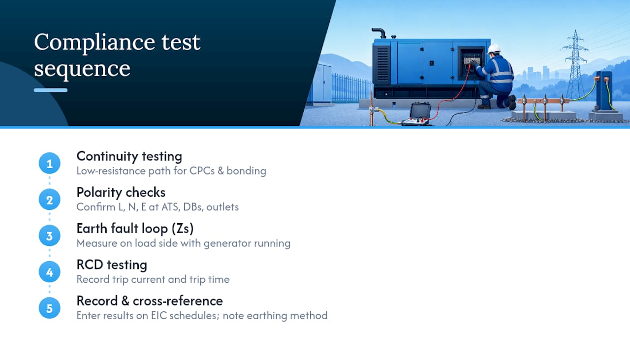
Earth fault loop impedance (Zs) testing has a place here too, but only on the load side of the installation once the generator is running and referenced, never as a substitute for electrode resistance testing on the generator’s own earth. RCD testing rounds out the sequence: trip current and trip time both need recording, not just a pass or fail indicator, because a device that trips at 200 mA when the specification called for 100 mA has technically “worked” and still failed to meet the design.
Every one of these results belongs on the EIC’s Schedule of Inspections and the Schedule of Test Results, cross-referenced against the specific earthing method used for that job. Our bonding versus earthing guide covers the distinctions installers most often blur when filling in that paperwork.
What health and safety risks apply to generator earthing work?
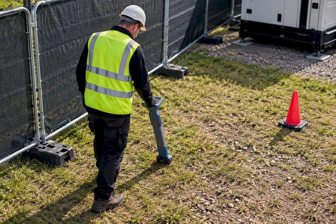
Driving and testing earth electrodes is manual, outdoor work, often on uneven ground, and it carries its own hazards separate from the electrical risk. Striking buried services while driving a rod is a real possibility on any site that hasn’t had a proper survey, so checking existing service records and using a cable avoidance tool before driving anything into the ground is standard practice, not an optional extra.
The electrical risk itself concentrates around two moments: connecting the earthing arrangement while the set is running, and testing it. Never work on the earthing connection or bonding while the generator is live and connected to load; isolate first, confirm isolation, then work. Test instruments used for electrode resistance testing can inject current into the ground during the test, so keeping bystanders and event guests clear of the test area matters as much as it does for any live electrical test.
Weather compounds both risks. Wet ground raises the chance of a slip while driving rods, and standing water around a test point changes the very resistance reading you are trying to measure accurately. On event sites specifically, the earthing point is often close to public footfall, cabling runs, or marquee groundsheets, so physically protecting the electrode connection and its test lead from foot traffic during the event isn’t just tidy practice, it prevents someone loosening a connection that was tested and signed off hours earlier.
Anyone maintaining a semi-permanent standby installation needs the same isolation discipline at every service visit, not just at first commissioning. A generator that has been running unattended for months is not obviously safe to approach at the earthing terminal just because it passed its test on day one.
Does generator earthing affect EMI and EMC performance?
It can, and the effect gets more noticeable as event and venue installations pack in more sensitive electronics, LED lighting drivers, digital mixing desks, networked control systems, all sharing the same power and earthing infrastructure. A poorly referenced or genuinely floating generator gives high-frequency noise nowhere consistent to go, and that noise can show up as flicker in dimmed lighting, audible hum on audio systems, or intermittent faults on networked control gear that are maddening to trace back to their source.
A properly referenced earthing arrangement, one electrode, one clear bonding path, gives switched-mode supplies and capacitive loads a defined route to earth for the leakage currents they generate, which generally settles this kind of interference. Multiple earthing paths created by mistake, for instance where a generator’s electrode and a building’s PME earth end up connected via bonding that wasn’t meant to bridge the two systems, tend to make EMC problems worse rather than better, because they create the circulating current loops the IET’s guide to temporary power systems specifically warns about when generators are paralleled or hybridised with battery storage.
The practical mitigation is straightforward even where the underlying physics gets complicated: keep the earthing and bonding topology as clean and single-path as the standards intend, avoid unnecessary parallel earth connections, and treat any unexplained flicker or hum on a generator-fed rig as a prompt to check the earthing arrangement before reaching for a filter or isolating transformer as a workaround.
Practical perspective: balancing ideal earthing with event constraints
Floating with a time-delayed RCD is a legitimate control, not a shortcut, but only for the duration it’s meant to cover: one event, one booking, documented as a deliberate choice rather than a default. If ground conditions make an electrode genuinely impossible and you can’t hit a defensible RCD setting, the right call is to say no and reschedule the power, not to energise and hope. Tell the organiser plainly what control is in place, why, and what its limits are; a client who understands the residual risk is a client who won’t be surprised by it later.
— Rob
How Jaks Party Power supports compliant generator earthing
Getting this right on a live event site, often overnight, sometimes in a field with no prior ground survey, is exactly where regulation meets the reality of event start times. Specialist providers exist to close this gap: generator hire, ATS and changeover installation, earthing design and commissioning, and standby cover throughout the event, ideally handled by the same team rather than stitched together between suppliers.

It is important that every job leaves with signed commissioning records referencing relevant standards such as BS 7671, BS 7430 and BS 7909, so the paperwork trail is sorted before the event begins. If you’re planning a generator installation anywhere across Sussex and want a site survey before you commit to an electrode design or a floating control, get in touch through our services page or check current generator hire options directly.
Sources
- Island‑mode earthing arrangements — IET Wiring Matters (March 2021)
- Operation of portable generators — IET (2011)
- MythBusters #6 — IET Wiring Matters (September 2020)
- BS 7430:2026 — BSI knowledge
- Legislation
FAQ
Does a generator need to be earthed?
Yes, when it operates as a standby or switched alternative supply, BS 7671 Regulation 551.4.3.2.1 requires an independent means of earthing rather than reliance on the distributor’s earth. Where an electrode is not achievable, a time-delayed RCD at the generator output rated no more than 100 mA is an accepted short-term alternative.
What are the current earthing regulations in the UK?
BS 7671 sets the core requirements, with BS 7430 covering electrode design and testing and BS 7909 covering temporary entertainment power specifically. Recent revisions, including BS 7430:2026, mean installers should always check they’re working from the current edition.
Do generators need to be grounded?
If “grounded” means earthed in the sense of Regulation 551.4.3.2.1, then yes for any set acting as a switched alternative to the mains. A genuinely floating set won’t trip on a single fault, but connected equipment still needs a proper fault path, which is why floating is accepted only as a controlled, time-limited measure with RCD protection.
Can I plug a generator into my house in the UK?
Connecting a generator directly into a domestic installation without a proper changeover switch is dangerous and against the requirements in Part 5 of BS 7671, since it risks back-feeding the network and bypassing the earthing arrangement entirely. Any standby connection needs a correctly specified ATS, either three-pole or four-pole depending on the earthing strategy, installed and certified by a competent electrician; this is a job for a qualified contractor, not a DIY extension lead.