

Use VD = (mV/A/m × Ib × L) / 1000 to find the voltage drop in a circuit, then check it against BS 7671: 3% for lighting circuits and 5% for everything else, which correspond to voltage limits based on the supply voltage. Get the mV/A/m figure wrong, or forget the check altogether, and you end up with dim lamps, hot cable, or a generator that trips under load.
TL;DR:
- Correctly matching the mV/A/m value to the specific cable size and installation method is crucial to ensure accurate voltage drop calculation.
- Using the formula without reactance considerations is suitable only for small conductors; larger cables and motors require accounting for resistance and reactance, which can significantly affect VD.
- Maintaining a margin of at least 10% below the maximum allowable voltage drop ensures reliable operation during unexpected load variations or measurement discrepancies.
- Verifying calculations with real-world measurements under load can reveal loose connections or undersized cables that may cause unexpected voltage drops.
- For complex or large circuits, consulting a qualified electrician to verify and adjust the power system setup before an event is highly recommended.
Table of Contents
- How to calculate voltage drop step by step
- What does BS 7671 actually require?
- When does the simple formula fall short?
- Worked examples: lighting, three-phase and 12 V DC
- How do you measure voltage drop under load?
- How do you fix excessive voltage drop?
- Applying voltage drop calculations to event power
- Why margin matters more than precision at events
- Getting your power calculations verified before the event
- Sources
- FAQ
How to calculate voltage drop step by step
The mV/A/m method is what most electricians use for a quick, reliable answer, and it’s the same approach behind every online cable length voltage drop calculator you’ll find. The three variables are:
- mV/A/m: the millivolt drop per amp per metre for a specific cable, taken from a manufacturer’s table or BS 7671’s own tables.
- Ib: the design current, meaning the actual current the circuit will carry in normal use, not the fuse rating.
- L: the one-way route length in metres from origin to load, not the round trip.
Once you’ve got the three figures, the process is straightforward:
- Multiply mV/A/m by Ib by L.
- Divide the result by 1,000 to convert millivolts to volts.
- Divide that voltage figure by the supply voltage and multiply by 100 to get VD%.
- Compare VD% against the 3% or 5% limit depending on circuit type.
Most calculators ask for the same three inputs, so reproducing their output by hand is mostly a case of getting the mV/A/m value right for your exact cable size and installation method.
What does BS 7671 actually require?
BS 7671 regulation 525 sets the ceiling: 3% for lighting circuits and 5% for other circuits, which works out to 6.9 V and 11.5 V respectively on a 230 V supply.
At a glance: 3% lighting drop maximum and 5% other circuits drop maximum, both based on the nominal supply voltage.
The mV/A/m values themselves live in Table 4Ab and Appendix 4, which break figures down by conductor size, insulation type and installation method. A handful of points worth flagging:
- Private supplies and generator-fed installations get some latitude under the regulations, since voltage regulation on a genset behaves differently to the grid.
- Voltage drop is cumulative: a submain eating 2% leaves only 3% for the final circuit if you’re working to the 5% ceiling.
- Ring final circuits use a different worst-case method (a midpoint assumption) that gives a lower figure than treating the ring as a simple radial.
- Cable manufacturers publish their own mV/A/m tables too, and these sometimes differ slightly from the generic BS 7671 figures, so match the table to your actual cable, not a similar one.
When does the simple formula fall short?
The basic mV/A/m formula assumes a purely resistive cable, which is fine for smaller conductors on typical domestic and event loads. It stops being fine once you’re dealing with big submains, motors, or long three-phase runs, because the AC formula needs to account for reactance:
VD = Ib × L × (r × cosφ + x × sinφ) / 1000
Here, r is resistance, x is reactance, and cosφ is the power factor of the load. sinφ comes from the same power factor figure.
A few things to watch for:
- Reactance (x) becomes significant once conductors reach roughly 25 mm² and above, so ignoring it on smaller cables barely matters.
- Three-phase circuits sometimes need the √3 factor built into the calculation, or phase-specific tables, depending on how the load is balanced.
- Motors and other low-power-factor loads shift the balance between the resistive and reactive terms noticeably.
Pro Tip: If you’re sizing a submain feeding motors or large distribution boards, pull the manufacturer’s r and x figures for that specific cable rather than relying on a generic resistive-only table.
Worked examples: lighting, three-phase and 12 V DC
Numbers make this concrete faster than any explanation, so here are three scenarios you can adapt directly.
- Single-phase lighting circuit: 6 mm² cable, mV/A/m of 7.3, Ib of 20 A, run length 25 m. VD = (7.3 × 20 × 25) / 1000 = 3.65 V. As a percentage of 230 V that’s 1.6%, comfortably inside the 3% limit.
- Three-phase submain: 16 mm² cable, mV/A/m of 2.8, Ib of 63 A, length 40 m. VD = (2.8 × 63 × 40) / 1000 = 7.06 V, or 3.07% of 230 V. That leaves room for the final circuit if you’re working to the 5% total.
- 12 V DC accessory circuit: 2.5 mm² cable, mV/A/m of 18, Ib of 5 A, length 8 m. VD = (18 × 5 × 8) / 1000 = 0.72 V. That looks trivial in volts, but the percentage voltage drop may be significant at low supply voltages. Percentage, not raw volts, is what matters at low voltage.
The Total Skills UK guide walks through similar checks if you want to sanity-test your own figures against another worked source.
How do you measure voltage drop under load?
Calculation is only half the job. To verify it, measure the voltage at the origin (consumer unit or distribution board) and at the far end of the circuit, both under the same load conditions. The difference between the two readings is your real-world voltage drop.
Use a true-RMS meter if the load includes dimmers, variable-speed drives or other non-sinusoidal equipment, because a standard averaging meter will misread those waveforms. Isolate circuits where you safely can, and leave live measurements on energised distribution to a qualified electrician.
- Expect small differences between measured and calculated figures, often from cable temperature, connection resistance, or the load being lighter than the design current assumed.
Pro Tip: A big gap between measured and calculated voltage drop usually points to a loose connection or undersized cable somewhere in the run, not an error in your maths.
How do you fix excessive voltage drop?
Once a calculation fails the 3% or 5% check, you’ve got a limited set of real options, and they all trade off cost against convenience:
- Increase conductor size: going from 6 mm² to 10 mm² on a run typically cuts voltage drop by around 40%, since mV/A/m falls roughly in proportion to cross-sectional area.
- Shorten the route or relocate the distribution point: moving a board closer to the load has an immediate, linear effect on VD, since L is a direct multiplier in the formula.
- Split the load across multiple runs: two smaller cables in parallel each carry less current, which reduces the Ib term for each individual run.
- Move to three-phase or higher-voltage distribution: for genuinely long distances, distributing at a higher voltage and stepping down locally avoids the problem altogether rather than fighting it with bigger cable.
If a fix means uprating a distribution board or adding additional cable runs, that’s the point to bring in a qualified contractor rather than guessing at a workaround.
Applying voltage drop calculations to event power
Event loads rarely run at their full rated draw simultaneously, so most practitioners apply a diversity factor, typically 40–60%, rather than summing every piece of equipment’s nameplate figure. That single decision changes the cable size you actually need.
At Jaks Party Power, checks on temporary distributions usually include:
- Confirming generator voltage band settings suit the connected load, not just its rated capacity.
- Sequencing large loads (catering, lighting rigs, sound systems) so they don’t all start simultaneously and spike demand.
- Running load-bank testing on generators before an event to confirm they hold voltage under realistic draw.
Anyone specifying distribution boards for a multi-day event benefits from applying the same conservative logic Rob uses when reviewing site plans.
Why margin matters more than precision at events
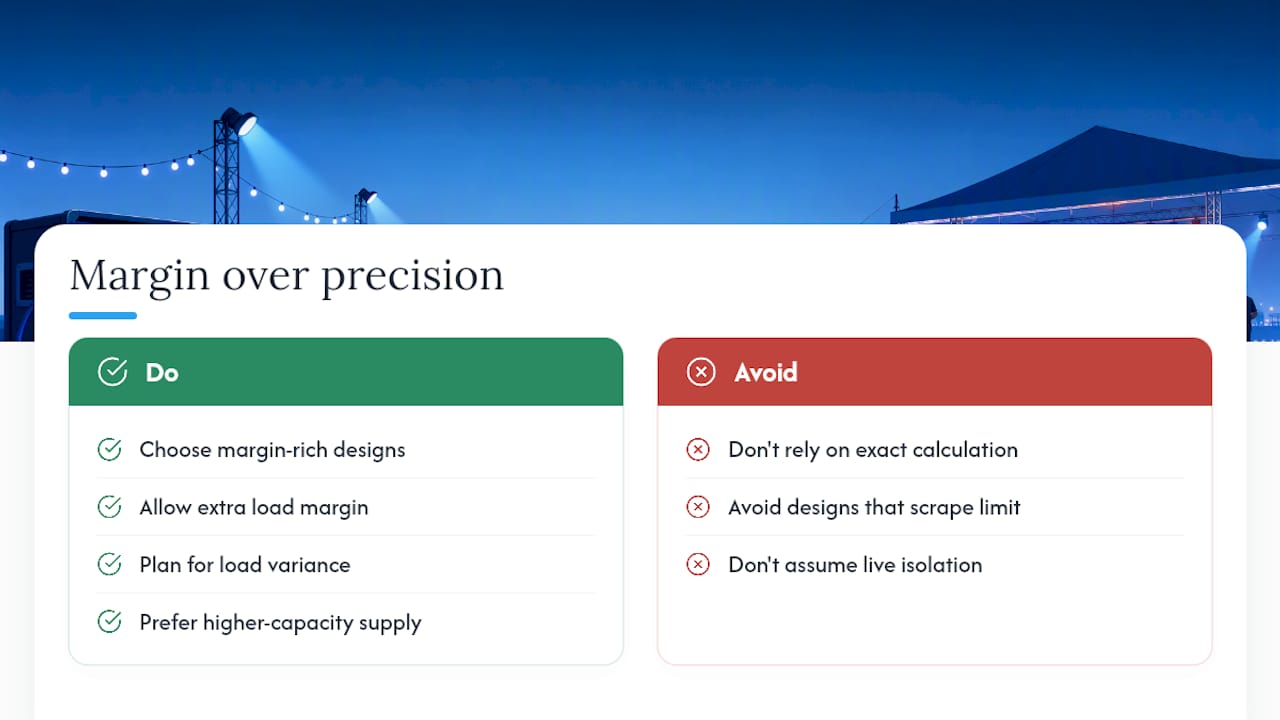
Voltage drop rarely fails an installation outright. It fails it slowly, through dimming lights, a motor running hotter than it should, or a generator hunting to hold its band under a load it technically has capacity for. Calculations get you close; margin is what protects you when the load on the night doesn’t match the load on paper.
Given the choice between a calculation that scrapes under the limit and one with room to spare, always take the one with room to spare, especially for events where you can’t isolate a circuit mid-show to fix it.
— Rob
Getting your power calculations verified before the event
Getting the mV/A/m sums right on paper is one thing. Getting them right for a three-phase submain feeding a marquee, a stage rig and a catering unit on the same night is another. Jaks Party Power specialises in exactly that gap: generator hire, distribution boards, cable runs and standby electricians who can verify a calculation on site rather than leave you trusting a spreadsheet.

That’s the value of over 40 years of electrical contracting experience behind an event: when a load looks borderline on paper, someone on site can measure it under real conditions and adjust before it becomes a problem. If your event involves three-phase supplies, large lighting rigs or multiple distribution points, it’s worth engaging that kind of verification rather than relying on hand calculations alone.
Start by checking generator options for your event size, or get in touch through Jaks Party Power to talk through your specific load and distribution plan before you commit to a cable spec.
Sources
- BS 7671 regulation 525: voltage drop | ECalPro
- Volt drop calculation: formula, 3% & 5% limits (BS 7671) | Total Skills UK
- Voltage drop in wiring: what it is and when it matters | VoltCalcs
- Calculating voltage drop with NICEIC | Professional Electrician
FAQ
What is the formula for voltage drop?
The standard UK formula is VD = (mV/A/m × Ib × L) / 1000, where mV/A/m comes from BS 7671 tables, Ib is the design current, and L is the one-way cable length in metres.
How do I calculate voltage drop according to BS 7671?
Apply the mV/A/m formula, convert the result to a percentage of supply voltage, then check it against the BS 7671 limits of 3% for lighting circuits and 5% for other circuits.
How do you calculate volt drop in a UK electrical circuit?
Take the mV/A/m figure for your cable from Appendix 4, multiply by the design current and the one-way route length, then divide by 1,000 to get the drop in volts.
What is the voltage drop on a 20 amp circuit?
It depends entirely on cable size and length rather than the current alone.